Annoy-o-Tron
What is that high pitched beep I can hear every few hours?
The Annoy-o-Tron is a small little device wich I developed together with a friend to teach him the basics of electronics and microcontrollers. Why a device to annoy people? Because trolling is fun! (evil grin)
Wanna build your own? Let's get started!
Electronics
The schematic is rather simple and consists of a ATTiny13 connected to a 3V lithium coin cell (with a 10µF capacitor in parallel to it to provide power for the short beep even if the battery is running low) and a piezo speaker connected to pin 5 (PB0). This piezo speaker should be a "dumb" one as the PWM for the beep comes from the ATTiny.
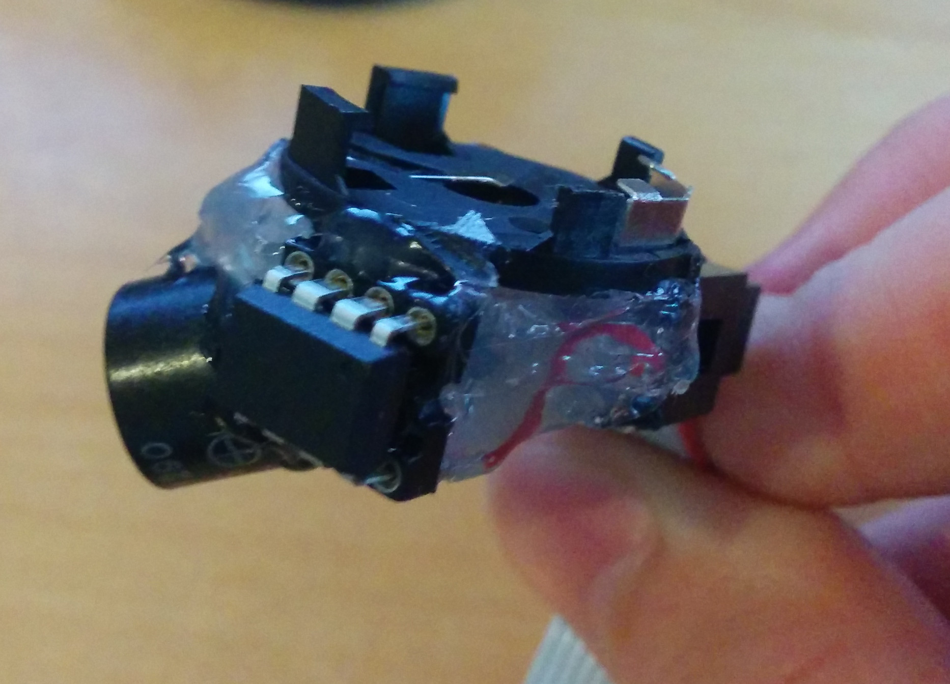
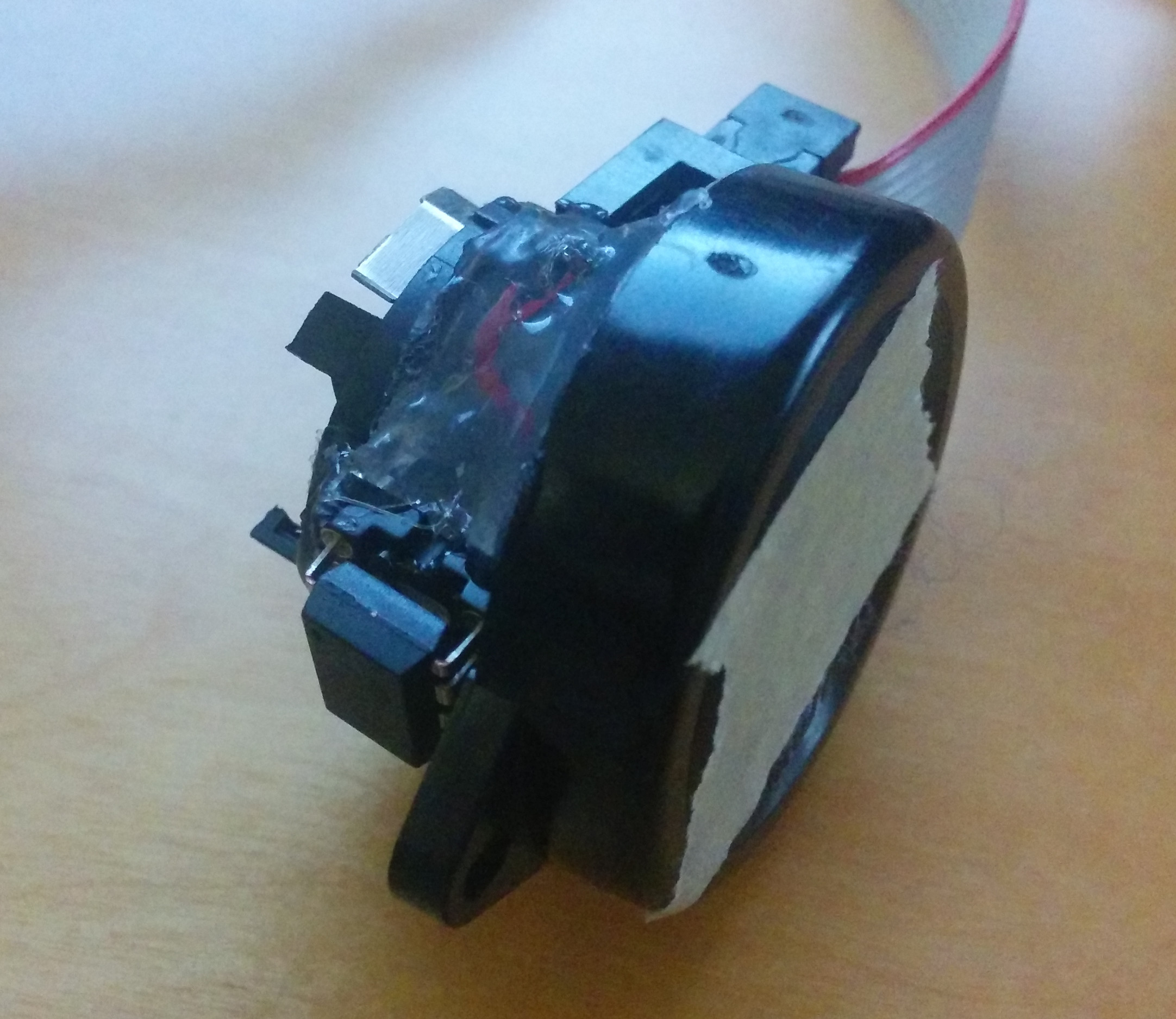
After a bit of testing we came to the conclusion that the small piezo you can see on the left is too silent and not annoying enough so we setteled for a bigger version you can see below.
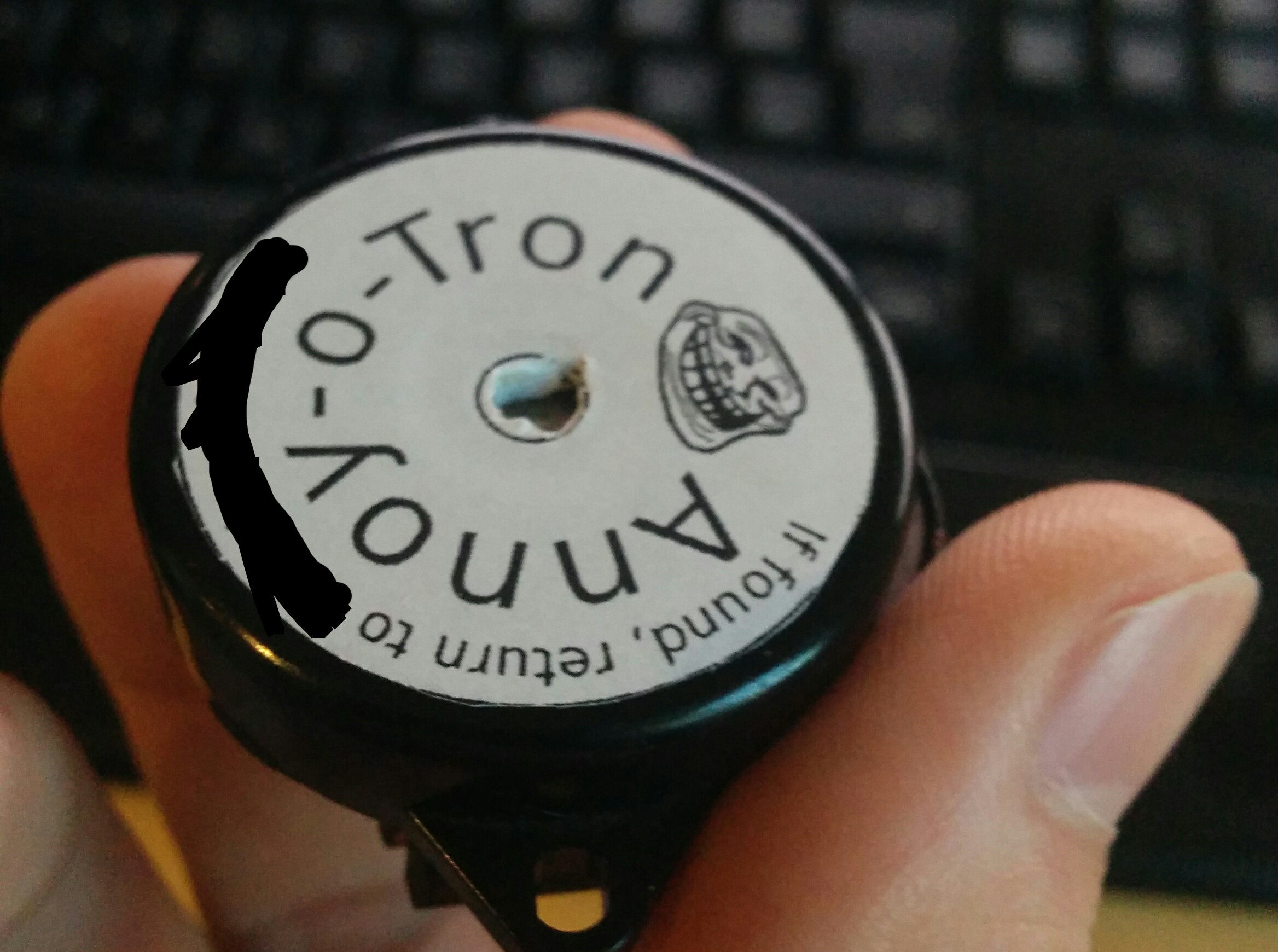
Now that everything was working as expected all that was left was to optically fine tune the thing to look like a REAL troll!
Software
The software basically puts the processor into deep-sleep for a random time, wakes up, beeps and sleeps again. If you don't care how it works you can scroll down where you can find a zip with all project files.
First things first: Setup the processor and all its peripherals and start the main loop.
int main() {

#ifdef DEBUG
    DDRB |= _BV(PB3); // Debug LED
#endif

    // Disable analog comparator to save power
    ACSR &= ~_BV(ACIE);
    ACSR |= _BV(ACD);

    // PWM
    TCCR0A |= _BV(COM0A0);
    TCCR0A |= _BV(WGM01);
    OCR0A = 3;

    // Globally enable interrupts
    sei();

    // Beep once to show that everything is working
    start_speaker();
    wd_short();
    wait_idle();
    stop_speaker();

    // Main loop
    for (;;) {
        uint16_t time = random_time();
        for (uint16_t i = 0; i < time; i++) {
            wd_long();
            wait_sleep();
        }
        start_speaker();
        wd_short();
        wait_idle();
        stop_speaker();
    }
}
If the DEBUG flag is set, the first thing the firmware does is setting pin 2 (PB3) as output, which we used to connect a LED to debug the deep sleep and wakeup routines. To save energy we also disable any unnecessary peripherals such as the analog comparators.
To be annoying we use the internal timer to generate PWM at 16kHz (128kHz clock, no prescaler, toggle if counter/timer counts to 3) which is disabled at this point.
Now let's take a look at how the sleep mode works:
void wait_sleep() {
    sleep_enable();
    set_sleep_mode(SLEEP_MODE_PWR_DOWN);
    sleep_cpu();
}

void wait_idle() {
    // Prescale = 32k
    sleep_enable();
    set_sleep_mode(SLEEP_MODE_IDLE);
    sleep_cpu();
}


void wd_short() {
    reset_wd();
    WDTCR |= _BV(WDP2);
}

void wd_long() {
    reset_wd();
#ifndef DEBUG
    WDTCR |= _BV(WDP3) | _BV(WDP0);
#endif
}

void reset_wd() {
    WDTCR |= _BV(WDTIE);
    WDTCR &= ~(_BV(WDP3) | _BV(WDP2) | _BV(WDP1) | _BV(WDP0));
}
The first thing you have to do is selecting how long to sleep by resetting the watchdog wakeup time register bits and then setting it to either short (0.25s) or long (8s). After you've setup everything correctly you then have to choose a sleep mode. In our case deep sleep for the "long sleep" as it disables all peripherals and therefore saves power and idle sleep for the "short sleep" as it allows the PWM to continue to work (which we need for beeping). The DEBUG flag sets the duration for a long sleep to a much smaller value allowing you to test your code without waiting hours (quite useful :P).
Two important things I learned about the sleepmodes are that first, for wakeup to work you have to have interrupts enabled and that an interrupt service routine has to exist (even if this interrupt service routine is empty) and second that after waking up from any sleep mode the processor continues directly where it left off before going to sleep (in our case directly after the sleep_cpu call).
The second important part is controlling the piezo speaker which is handled by the following functions:
void start_speaker() {
    // Our speaker is on PWM 0 so we need it as output
    DDRB |= _BV(PB0);
#ifdef DEBUG
    PORTB |= _BV(PB3);
#endif
    TCCR0B |= _BV(CS00);
}

void stop_speaker() {
#ifdef DEBUG
    PORTB &= ~_BV(PB3);
#endif
    TCCR0B &= ~_BV(CS00);
    DDRB &= ~_BV(PB0);

}
start_speaker sets pin 5 (PB0) as output and starts the counter to produce PWM. If the DEBUG flag is set it also enables the LED on pin 2 (PB3). stop_speaker just reverses the process mentioned above.
Last but not least the main loop calls random_time:
static uint8_t cnt8 = LFSR_SEED;
static uint8_t prng_lfsr8(void) {
    return (cnt8 = (cnt8 >> 1) ^ (-(cnt8 & 1) & 0xB4));
}

uint16_t random_time() {
    // 30 min to ~3.2h
    return (1800 + ((uint16_t) prng_lfsr8()) * 38) / 8;
}
This function calls a linear feedback shift register which is a very simple PRNG and uses the returned pseudorandom value to determine the length of the next sleep cycle.
Back to the main loop we fit all the pieces together:
    for (;;) {
        uint16_t time = random_time();
        for (uint16_t i = 0; i < time; i++) {
            wd_long();
            wait_sleep();
        }
        start_speaker();
        wd_short();
        wait_idle();
        stop_speaker();
    }
This loop just waits a random time (between 0.5 and 3.2 hours), beeps for 0.25s and repeats the whole process.
Download
All project files you need to replicate this (code, makefile, precompiled hex file and pictures) as a handy zip file ready to annoy anyone you'd like: annoy-o-tron.zip